Describe Lcd Module Interface Using 4 Data Pins
LCD connections in 4-bit Mode Above is the connection diagram of LCD in 4-bit mode where we only need 6 pins to interface an LCD. This post will deal the programming of LCD in 4 bit mode with the RW line of the LCD pulled low.
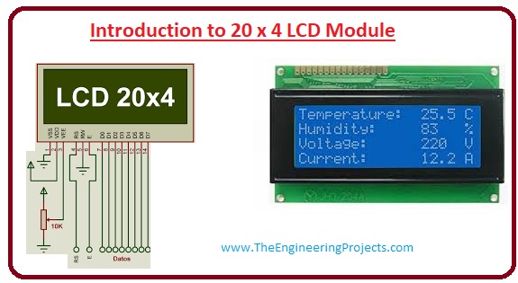
Introduction To 20x4 Lcd Module The Engineering Projects
Because we need to supply 5v to LCD SDA pin of I2C is connected D4 of the NodeMCU.

. To interface LCD to the AVR we can use 4-bit mode and 8-bit mode. Therefore in total an LCD interface will need 11 83 or 7 43 pins of the microcontroller. We are not using ReadWrite RW Pin of the LCD as we are only writing on the LCD so we have made it grounded permanently.
The user may select whether the LCD is to operate with a 4-bit data bus or an 8-bit data bus. Read and Write Mode of LCD. You can connect the LCD to any of the PORT pins available on your boards and update this section accordingly.
Connect GND Ground of Arduino VCC 5V Arduino Pin SDA SDA Pin of Arduino mentioned in the backside of Arduino. Specifically low pin count MCUs need to operate in the 4-Bit mode. No control pins are used to set these modes.
The MCU can either read or write to this interface IC. As said the LCD itself consists of an Interface IC. The rest 2 pins for power supply Vcc and groundThere is a POT on the I2C Module.
Using 4-bit transfers means we only need one port dedicated to the LCD. Pin 1 is GND and is connected to the GND available on Launchpad. The LCD I2C Backpack only has 4 Pins.
Power Pins 8-bit Data Pins SPI Pins 24 TFT Module Feature The single TFT LCD can view the whole image in colors with 240320 pixels max. They are GND Ground VCC 5V Power Supply SDA Data Line SCK Clock Line Circuit diagram. And there is a jumber fixed on the module.
This saves us 4 pins. And the connections are as follows. TFT LCD is operatable with both 5 and 33V power input.
SCL pin of I2C is connected D3 pin of the NodeMCU. The 8-bit data interfacing is easier to program but uses 4 more pins. Heres the circuit diagram.
Interface an LCD with 8051 in 4 bit mode Use a single port of the microcontroller for both data and control lines of the LCD. If the RW pin is connected to the ground the LCD can be used to write data only. The 16x2 has a 16-pin connector.
The 16 pins for connect to 16x2 LCD and the 2 pins out of 4 pins are SDA and SCL. 16x2 LCD Module Pinout. The LCDs registers from D0 to D7 and Vcc GND RS RW pins will be connected to I2C.
To use more than one device it is necessary to jumper them all uniquely. But the rst 14 pins still serve as the interface. Because in 8-bit mode you write the data in just one go.
SDA is the serial data pin and SCL is the clock pin. LCD Module to 8051 4 Bit Mode As shown in the circuit diagram port 0 of the controller is used for interfacing it with LCD module. We can control the contrast of the LCD display by rotating this POT.
If a 4-bit data bus is used the LCD will require a total of 7 data lines 3. This pin regulates the. Reading from it is not possible.
VCC pin of I2C is connected Vin pin of the NodeMCU. One of the reasons why you would be using a serial LCD is the fact that it uses only 4 PINS instead of 16. Pin 3 is the LCD Display Bias.
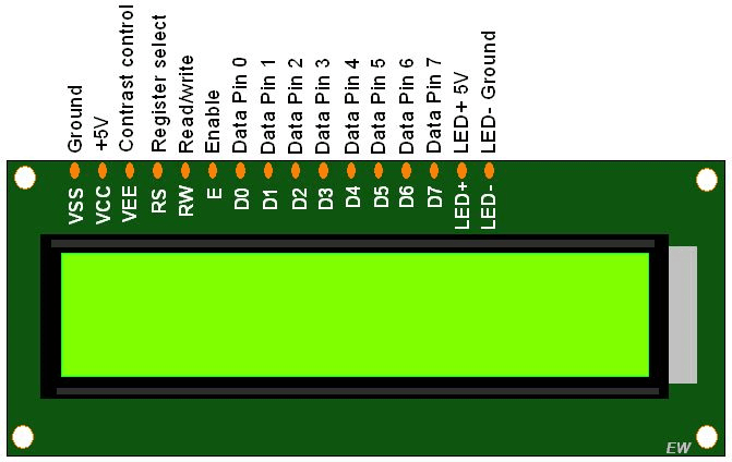
The pin configuration is as follows. The LCD display module requires 3 control lines as well as either 4 or 8 IO lines for the data bus. Table 1 contains the address assignments for ports A B C and the Control Register CR.
The process of sending data to be displayed to LCD. The higher nibble is sent first and then the lower nibble is sent to make one complete data transfer. The 8255 PPI chip can operate in three different modes 3.
You can use the full bus width 8-Bits for data or alternatively you can use a 4-Bit interface for a reduced pin count needed to control the LCD. The connection is simple just attach the LCD Backpack as shown in the image Pins coming outwards. This will make us run out of IO pins on our MCU so 4-bit mode is widely used.
It is possible to further reduce the total number of port pins required from 7 43 to 6 42 by shorting the RW pin to ground. The rst three pins are used provide power to the LCD module. There are also instruction command codes that can be sent to the LCD to clear the display or force the cursor to the home position or blink the cursor.
The following code will help to display the data. Port Connection This section shows how to configure the GPIO for interfacing the LCD. This means only four of the digital input lines DB4 to DB7 of the LCD are used.
LCD stores the received data in the data resistor since the. As we are interfacing the LCD in 4-bit mode only the higher 4 data lines are used as the data bus. In the library method the data and other pins will be set once and the remaining will change through programming.
8-Bit Interface 4-Bit Interface How To Setup Write To LCD 1. Had we used 8 bit data transfers we would then need another port for the RS and Enable bits. LCD receives data on the data bus.
In 4 bit mode only 4 lines D4-D7 along with RS RW and E pins are used. Pin 2 is VCC and it is connected 5V VBUS available on the Launchpad. Left alone they generate part of the F or 7 part of the address.
Arduino sets RS pin to HIGH to select data register Arduino writes data to D4 D7 pins data bus. And here are the pins and corresponding functions. Difference between 4-bit and 8-bit mode Its faster to use 8-bit mode as it takes half as long to use 4-bit mode.
The library method will send the data with the use of four pins mostly. This is a GND pin of display used to connect the GND terminal of the microcontroller unit or power source. The module can be used either in 4-bit mode or in 8-bit mode.
In this project the LCD module and arduino are interfaced in the 4-bit mode. The UART or serial module that is attached to the back of the LCD is responsible for sending and receiving serial communications between the Arduino and the LCD and it has a onboard potentiometer to adjust the brightness of the screen. D4-D7 are the data pins connection and Enable and Register select are for LCD control pins.
4 With the I2C backpack there are three pairs of landings A0 A1 A2 which determine the 3 LSB of the devices address using inverted binary. But HD44780 LCDs are designed in a way that we can talk to the LCD using only 4 data pins 4-bit mode instead of 8 8-bit mode. Potentiometer is connected to this pin to adjust the voltage.
3 Answers Sorted by. The 8 bit data is split up into two chucks of 4 bits each. The next table here incudes all the instruction command codes.
The signal on the chip-select CS pin will turn the chip on. There two communication methods for microcontrollers with LCD which are SPI and 8-bit data. 0x3F is common as is 0x27.
Hence this interface will just use 6 pins of the interface. The address lines A0 and A1 will select one of the four internal registers at one time. There are two ways to interface the LCD diver controller IC.
In 4-bit mode 4 of the data pins are not used and in 8-bit mode all the pins are used. The below configuration is as per the above schematic. This is the voltage supply pin of the display used to connect the supply pin of the power source.
The LCD module is wired to the Dragon12 so that it uses 4-bit data transfers the other pins of Port K being used for the RS Register Select and Enable bits. This method is very simple requires less connections and you can almost utilize the full potential of the LCD module. The 162 LCD pinout is shown below.
Its just the way of programming that change. GND pin of I2C is connected Ground pin GND of the NodeMCU.
Pin On Products

16x2 Lcd Module Arduino Projects Diy Electronics Projects Diy Lcd
Pic Interfacing Lcd 16x2 In 4 Bit Mode With Pic18f4550 Pic
No comments for "Describe Lcd Module Interface Using 4 Data Pins"
Post a Comment